
Peter's Nostalgia Site
If viewing with a smart
phone or tablet then turn it sideways for a better view.
Text in blue/pink are hyperlinks. Click on these for further information.
|
Peter's Nostalgia Site
Text in blue/pink are hyperlinks. Click on these for further information.
|
|
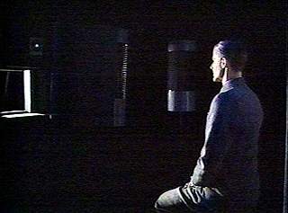
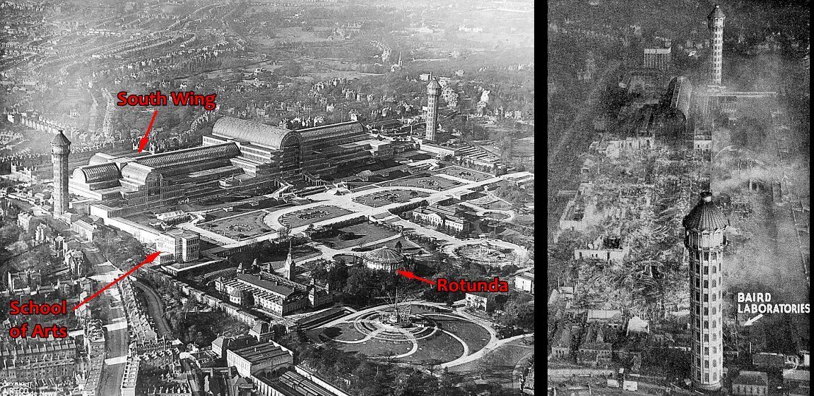
John Logie Baird & Baird Television Ltd. On the 9th of September 1930 the company "Television Limited" was wound up and all assets and patents were assigned to a new company "Baird Television Limited". This came about when the television activities of various Baird companies had run out of funding and by 1932 Isidore Ostrer and the Gaumont British Film Corporation had taken control of the company. Under Ostrer's control Sir Harry Greer was appointed chairman of "Baird Television Limited" (BTL) and in 1933 the technical leadership was removed from John Logie Baird (JLB) and Captain A.G.D. West appointed in his place. Although JLB still had a seat on the board and received funds from BTL he was left to experiment on his own ideas in a laboratory at his home and had little if any influence in the activities of BTL from 1933 onwards. The removal of JLB from the technical leadership was because the board of BTL were well aware of the Marconi-EMI's camera development and could see the writing on the wall for the mechanically scanned sources favoured by JLB. By early December 1936 the BBC had formed a clear impression of the superiority of the Marconi-EMI system over the BTL system in the Alexandra Palace trial and BTL also lost a large part of their premises at the Crystal Palace * due to the 30th November fire. The BBC decision to terminate the BTL studio and transmitter equipment was announced in early Februrary 1937. Public confidence in BTL nose dived. Shares lost considerable value and a large proportion of the staff were laid off. Apart from the production of domestic receivers West's team had also been developing high power projection sets for television presentations in theatres and independently JLB had developed a crude 120 line colour demonstration also for theatre display. These activities had impressed the Ostrer brothers and probably due to JLB's persuasive powers Gaumont British created a new company in February 1938 called Cinema Television. Had this not happened there is a strong possibility that Gaumont British would have withdrawn its support for BTL as share holders had to date not received any return on their investment. In the period up to the outbreak of war in September 1939 several Cinema Television demonstrations had taken place and the board of BTL were still pinning their hopes not just on the sales of domestic receivers but also the sales of Cinema Television equipment and the revenues from public attendances. No agreements were settled regarding licencing and royalties for Cinema Television and September brought a halt to all British television activity. Perhaps the board of BTL could have foreseen this but the result was that BTL went into receivership in November 1939. * Much of the BTL premises were located in the basement of the South Wing of the Crystal Palace over looking the terrace, which was destroyed although CRT and receiver manufacture were located in the Rotunda and School of Arts buildings respectively and fortunately remained undamaged by the fire as did the South Tower. Although not strictly relevant or accurate regarding television the history of the building is interesting. BTL Equipment used at the Alexandra Palace Trial As early as 1926 JLB could see that the amount of light captured on a photo cell by a Nipkow disc was severely limited even when the subject was lit by very powerful lamps. As a result he adopted the strategy of using the Nipkow disc in reverse such that it scanned the subject with a point of light from a powerful light source and collected the light reflected from the subject using a number of electron multipying photo cells arranged in positions similar to those of lights in a photo studio. The studio had white painted internal walls but was in total darkness apart from the scanned light beam. JLB achieved very much better results using this "Spotlight Scanner" and received a UK patent for the idea.
(During the post-war development of colour television in the US one company proposing a field sequential technique suggested using a strobe light during the frame blanking interval to illuminate an otherwise darkened spotlight studio! An interesting approach but probably not welcomed by epilepsy sufferers.) Always looking to broaden his marketplace, in June 1929 JLB found willing partners in Germany in the form of Bosch, Ziess Ikon and Loewe who were all interested in sharing technology for the development of television. JLB took a 25% share in the new company called Fernseh AG along with his three partners. Fernseh AG were well aware that the Spotlight technique was limited to small indoor studio use and had developed a system of film scanning using the Nipkow disc. This film scanner combined with rapid film development was seen as a possible "live" television signal source in the absence of an electronic camera. When considering high definition television the use a disc was considered preferable to that of a mirror drum because of the much smaller masses to be controlled.
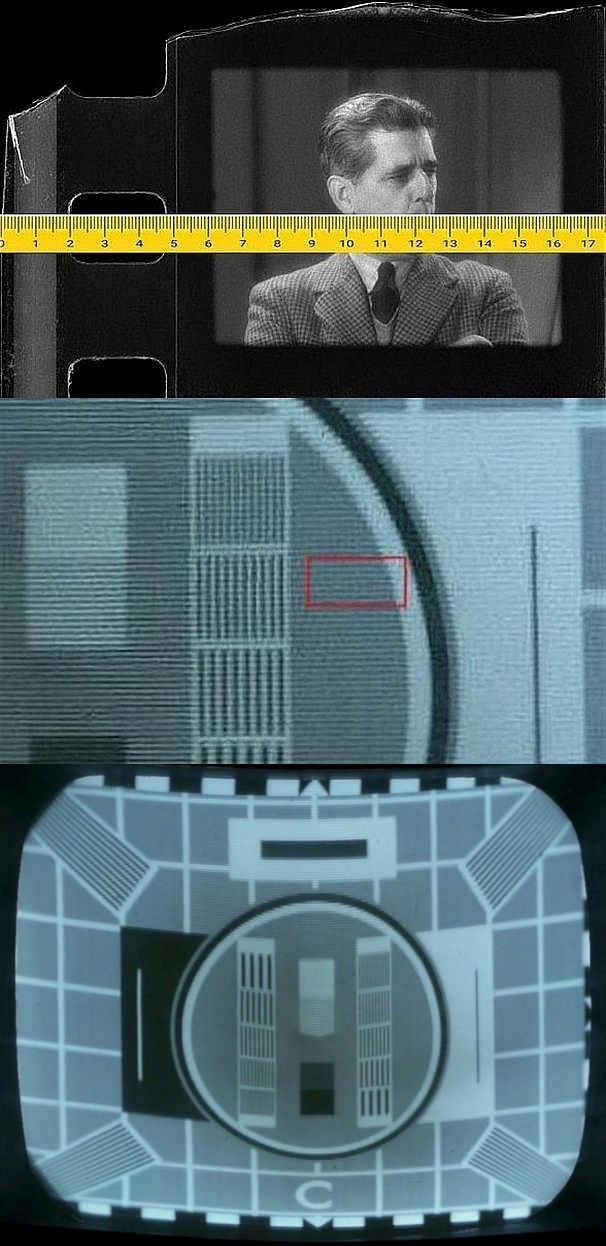
The Fernseh AG film scanning technology whilst very similar to that used for spotlight scanning did have a significant difference. In the spotlight scanner the full width and height of the subject needs to be scanned with the light beam and for example in the 240 line/25 Hz system the scanning disc was arranged to have four concentric spirals of 60 holes each, such that the full scan took four complete disc rotations and a second disc adjacent to the main one was run at a quarter of the speed, uncovering each of the four spirals in turn whilst blanking out the others. Segmenting the disc in this way makes it easier to reduce the overall diameter. The film used was 35 mm stock cut in half. The 17.5 mm frame size was 10 x 7.5 mm. Thanks to Steve Osler for correcting my first calculation of the line curvature that the disc scanning would generate. I agree with him that it would be 8.3 lines. Probably quite noticeable on images with straight horizontals. The close-up of the 240 line Test Card C shows a red box that is 8 lines high and gives an impression of how obvious the depth of distortion would be when viewed on a normal CRT receiver. The full Test Card C image might have looked curved as below if viewed on a CRT display. Thanks to Dicky Howett the original Vinten camera modified for use with 17.5 mm film in the BTL Intermediate Film machine was identified as still in existence. See the article in 405 Alive via the BVWS
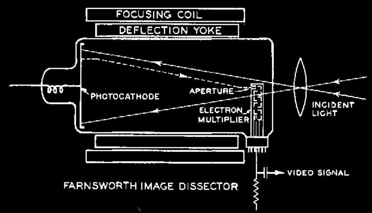
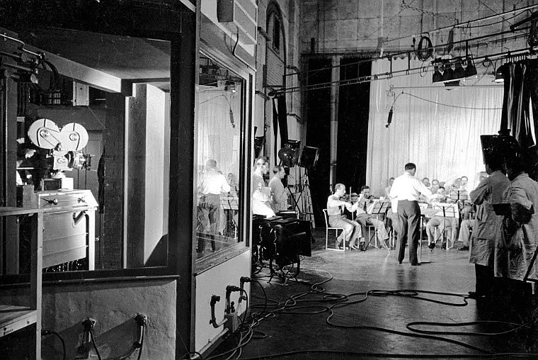
In the case of the telecine and intermediate film scanners it was only necessary to scan a single line so the holes in the scanning disc were set in a circle instead of a spiral and the secondary disc was only used to generate synch pulses. The vertical (frame) scanning was achieved by the continuous uninterrupted movement of the film. The film camera and sound recording camera along with the drive sprockets and synchronous motor were mounted on the lid of the developing tank. The tank had five compartments; developer, wash, fixer, wash then a scanning compartment still under water. A sixth compartment surrounded the tank with water kept at a constant temperature of 28C for best development. On each side of the tank there was a hydraulic ram used to lift the lid and camera assembly for replacing the film. The film magazines contained 1000 ft of film and so after 20 minutes of running, a new film needed to be loaded into the machine. Those tasked with this job and knowing the time pressures of "live" television would probably not have relished it especially given that some of the film guides were wet with the sodium cyanide fixer. After processing and having passed through the vision scanner the film sound track was read before being wound onto the receiving reel shown in the water trough in the photo above. Although the Vinten camera had the familiar "Micky Mouse" ears appearance the receiving reel on the camera was not used. The disc motor was water cooled and the disc and the motor were run in a vacuum. If either the water supply or vacuum supply failed an interlock shut down the motor. The Intermediate Film Camera and Scanner was located in a soundproofed booth at one side of the BTL Studio. The film scanning aspect was of course of interest to Gaumont British but Captain West and the board of BTL were well aware that fully electronic methods had overtaken mechanical ones and in 1934 found that Farnsworth, who was short of funds, was a willing supplier of electronic scanning technology/equipment in the form of the image dissector. In this device the photo electrons liberated from the photocathode at any point in the image were scanned past the very small aperture (0.015" diameter) of an electron multiplier and were only those from the instant of the scan. The system stood no chance against the sensitivity of the iconoscope/emitron where the photo electric elements were able to accumulate charge over the full period of the frame.
Apart from the lack sensitivity the Farnsworth cameras used by BTL also suffered from image distortion that turned the rectangular frame into something resembling a sausage shape. The use of this camera by BTL was really a measure of their desperation with the mechanically scanned sources and it came as no surprise to anyone that the BBC rejected the BTL system in favour of Marconi-EMI. A comparison is given here. The one advantage that the BTL system had over the EMI system was the lack of the image shading that required tilt and bend adjustments. This was especially true in the case of film transmissions where scene changes could be less predictable than those in the television studio. When Hitler came to power the alliance of Fernseh AG with a foreign company did not meet with approval and Baird Television Limited had to disassociate itself but Fernseh AG still continued to use the mechanical scanning and Farnsworth electronic scanning. Receiver Development at Baird Television Ltd Whilst Baird Television Limited didn't have a viable camera system and failed in the contest to provide studio and transmitting equipment for BBC Television they did have useful telecine equipment and they also offered good CRT receivers. Captain West had recruited an extensive team of engineers and technicians for the development of all aspects of electronic television. Quoting David Boynes:
"It is proven that the Baird TV
receivers were very well designed receivers, something I've always believed
having worked on both EMI and BTL models. I've always thought the Baird TV
receivers were much more advanced in design compared with the rather
ordinary circuits in the EMI sets. The T5 is a superhet which once the
problem of frequency changing is taken care of is much better than TRF
amplifiers because the input resistance of those early RF pentodes was very
low at 45mc/s. Much better to convert down to something like 10mc/s and
achieve much greater stage gains. The single valve timebases in Baird
receivers exploit the properties of inductors. The valve functions as a
switch and the sawtooth waveform ramps up in the transformer primary,
reaching the point where the flyback is initiated and the forward scanning
process repeats. The later T20 models used a damper diode in the line
timebase, something you never saw in an EMI set, except the studio monitors
of course. In terms of construction quality there's no doubt the EMI TV sets
are better made but I cannot find any sortcomings of the Baird receivers
either. OK, the EMI chassis are made from thicker gauge metal but does that
matter too much?"
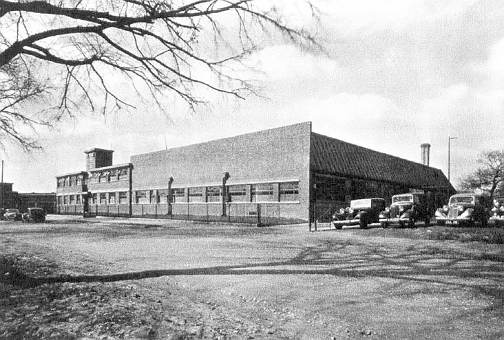
In October 1934 BTL had agreed to purchase technology from Farnsworth for $50,000. Although the purchase of the Image Dissector design had been abortive a further part of the deal was a licence agreement enabling BTL to manufacture copies of Farnsworth 15" magnetically focussed receiver cathode ray tubes. Dr C. S. Szegho (£550/year) was recruited by BTL in September 1934 in time to assess the technology purchase from Farnsworth. Under Szegho in the CRT development team were W.P. Anderson who designed and set-up the vacuum pumping stations, induction heaters and CRT test gear, also G.A.R. Tomes and Runham. Farnsworth came over with his engineers Rutherford and Brolly and they instructed Szegho on the mix of fluorescent screen materials and how to apply them and also how to construct CRTs with hot cathodes. Szegho's previous experience had been with Braun type tubes i.e. cold cathode. For the development of receiver circuitry BTL recruited L. R. Merdler (£750/year) and his team of G.R. Tingley, M. Scott and D.V. Ridgeway (GB512795 and more). Looking at the patents Merdler was mainly involved with the VHF receiver design (GB460221, GB459300, GB458133,GB466419,GB473896,GB475046,GB460198, GB462684 and more) and Tingley and Pugh (of the transmitter design office) the timebase development (GB456640, GB456666, GB457129 and more and more). The design and manufacture of the television receivers had taken place in the School of Arts building at Crystal Palace up until the fire on the 30th November 1936 but thereafter the School building and the South Tower accommodated most of the activities displaced from the destroyed South Wing and set manufacture was contracted out to Bush Radio who were another company controlled by Gaumont British. Models that included radio broadcast receivers used Bush Radio designs. It is not known where final assembly and test of receivers took place but this may have been at Bush Radio premises. In October 1937 most of the BTL activities moved to new premises in Worsley Bridge Road, Lower Sydenham.
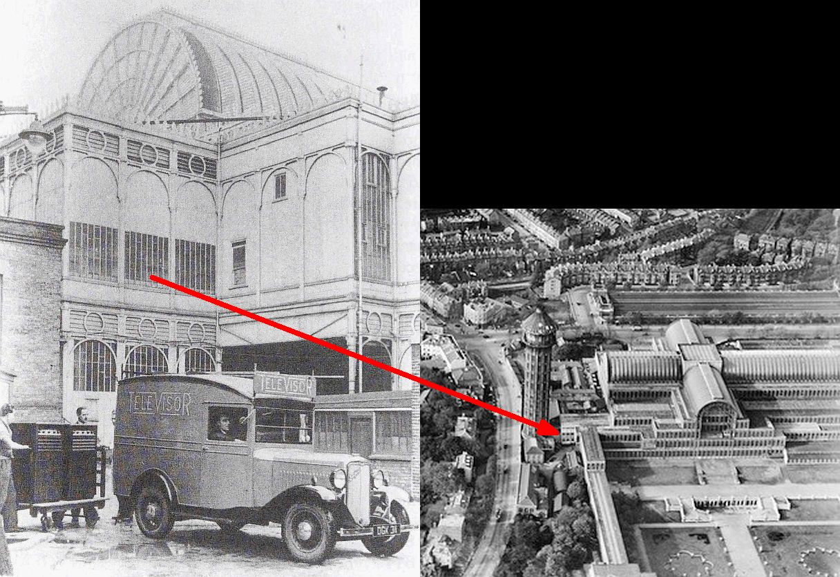
The part of the South Wing occupied by BTL research and experimental television studios was located beneath the garden side of the South Transept overlooking the terrace. Click on the drawing for a larger view with photos.
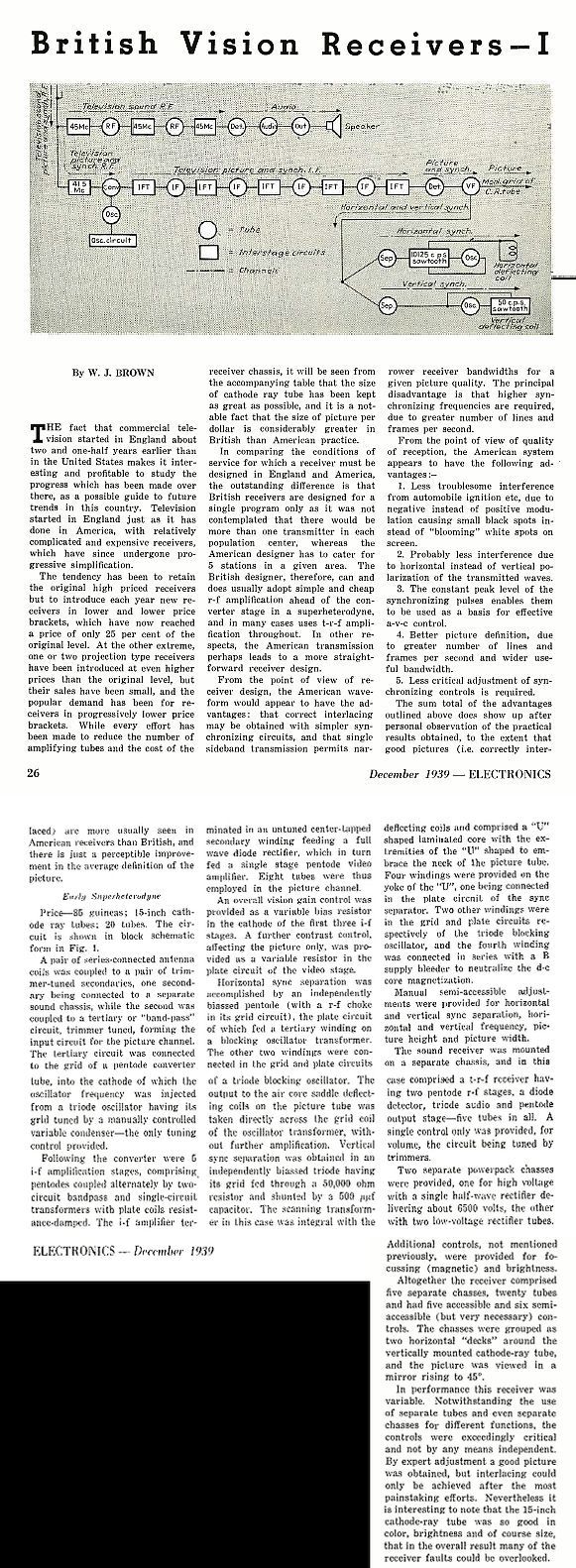
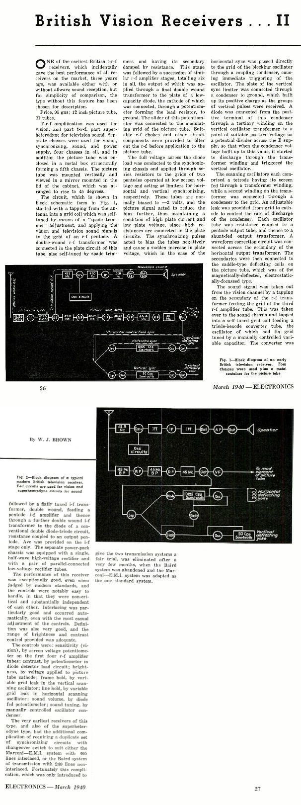
Acknowledgement to Douglas Brown The first BTL television receivers designed for the BBC broadcasts of 1936 were the T5, T6 and T7: T5: Television only set with 15" CRT viewed via mirror lid. Superhet receiver for both sound and vision. 20 valves. Walnut cabinet 43" x 23" x 19" HxWxD. In more recent times those operating the T5 are impressed by its performance but in 1939 W. J. Brown writing in the journal "Electronics" was rather less than impressed with the T5. Perhaps his set had a fault. In the second part of his article the author was more impressed by the EMI competitor product, the HMV 901 / Marconiphone 702.
A viewer in Welwyn (Captain Ernest H. Robinson) recorded his experiences in Wireless World viewing the BBC test transmissions on a T5 prior to the official November 1936 opening ceremony. He also wrote the book "Televiewing" published in 1935. T6: As for T5 but with 12" CRT. Superhet vision receiver and straight sound receiver and included a Bush Medium and Long Wave radio similar to the SAC21. 41" x 21" x 17" HxWxD.
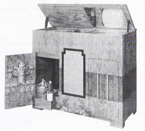
T7: As for T5 but included a Bush SSW 33 radio and an auto changing gramophone. 25 valves. 39" x 49" x 20" HxWxD. The photo below is actually of the T13 from a year later than the T7 but is similar in features.
|
.jpg)
.jpg)

.jpg)
.jpg)