
Peter's Nostalgia Site
If viewing with a smart
phone or tablet then turn it sideways for a better view.
Text in blue/pink are hyperlinks. Click on these for further information.
|
Peter's Nostalgia Site
Text in blue/pink are hyperlinks. Click on these for further information.
|
|
|
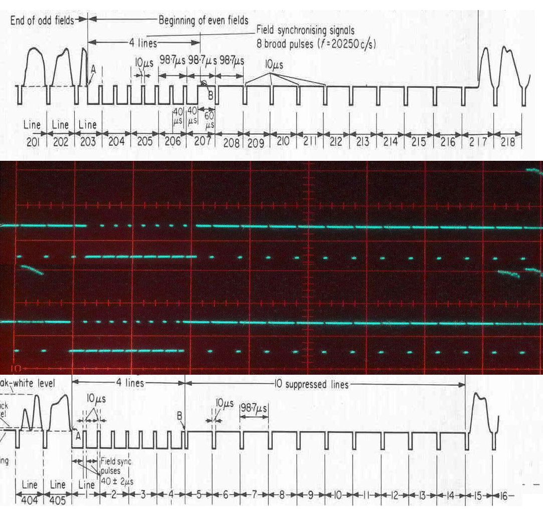
Alternative Sources of 405 line and 240 line A number of people have developed the use of PC graphics cards for presenting 405 line and 240 line signals to old televisions. Below is a description of the method I have used. I would like to acknowledge and thank some of those whose work has made this possible: Jeroni Paul for his PC application for graphics card control and for his very helpful assistance with the specifics, Kat Manton for conceiving the method, Jim Beacon for demonstrating the feasibility and Graham Rabstaff for demonstrating it from a PC. The scheme I have been using is simply a development of that devised by Graham Rabstaff. My methods differ regarding the sync pulse generation and also in the application of sources. The present scheme works well but doesn't generate the correct sync pulse stream in accordance with either the EMI 405 line standard nor the 240 line standard of the Baird system. The Baird system did not specify any line sync pulses during the frame pulse and receivers needed a method of maintaining correct line frequency in the absence of sync pulses. In the case of the EMI sets some additional circuitry and a valve (V8) was required to be switched in for 240 line operation. The graphics card source does continue to generate line sync pulses during the frame sync pulse so there is no need for the additional V8 circuitry. The graphics card syncs do differ in two respects from the EMI 405 line standard and this can cause rather critical line frequency adjustment or hooking at the top of the picture in older sets that don't have flywheel sync. The existing composite sync is simply generated by exclusive OR of the line and frame pulses but the resulting inverted line pulses within the frame sync are slightly delayed relative to their correct positions. There is also no half line pulse stream. The latter is not essential but a simple monostable circuit can correct the pulse positions and add the half line pulses. See Here. The use of monostables is not very exacting but the odd and even frame syncs shown below are what I am using and are a fair representation of the spec.
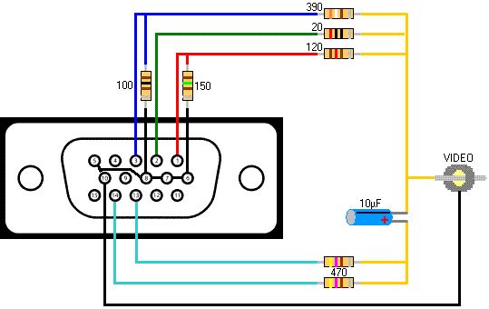
To use this circuit the Modelines need to be changed such that the Composite Sync box should be unticked and the +hsync references should become -hsync. Hardware Requirements 1. A graphics card with two VGA outputs. In practice this generally involves a card with a DMS-59 connector and splitter cable giving the DMS to 2 x VGA connectors. Before purchasing a graphics card please check the compatibility requirements in Jeroni Paul's website. One VGA output will support the PC whilst the other will connect to your television via a small VGA to composite video adaptor and a modulator to present the signal at the aerial socket. 2. A VGA to Video Adaptor. The adaptor can be as simple as the circuit shown in Jeroni Paul's notes:
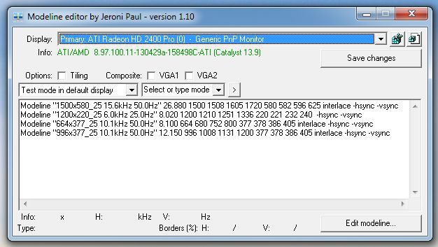
3. A Modulator. Various modulator circuits are available I am using the design from Darius' standards convertor 4. A Sound Signal. The sound signal is simply taken directly from the PC speaker output to the input of the sound modulator. 5. A PC with a PCIe x16 motherboard slot. Software Requirements Jeroni Paul's Modeline Editor VLC Player for Windows After downloading the Modeline Editor you will need to sign in to your PC as administrator and have ability to edit the registry. Having loaded the Modelines using Jeroni Paul's editor as in the first picture below, you don't need to use the Modeline Editor from now on. Please note that having entered the modelines your PC will reboot when you hit "Save changes".
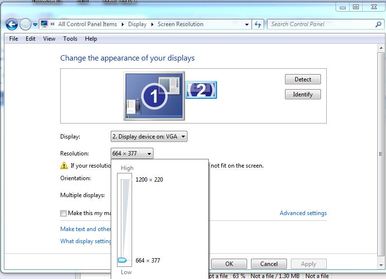
If you want to switch line rates then you use your Windows Control Panel, Display, Change Display Settings then select your Number 2 display and select the resolution you require. The PC does not require a reboot to make these changes.
If you want to display video material the freeware application VLC Player works very well. You do need to make a little change to the pixel aspect ratio and so I have two shortcut icons on my Windows Desktop both pointing to VLC Player.As normally loaded the Target in the shortcut might read: "C:\Program Files\VideoLAN\VLC\vlc.exe" For my 405 line shortcut to VLC Player I changed the Target to read: "C:\Program Files\VideoLAN\VLC\vlc.exe" --monitor-par=11:14 And for my 240 line VLC Player the Target is: "C:\Program Files\VideoLAN\VLC\vlc.exe" --monitor-par=11:45 Now if I want to display a DVD on a 405 line receiver I connect my Number 2 VGA port on the PC to my Channel 1 modulator and click on my 405 VLC Player. I select Media, Open Disc.. then in the new window "Play" and the DVD menu comes up in the window. I then drag that window over to the right and off my PC screen and into my TV screen. Then hit f to get full screen then position the cursor over the video to play and hit return. The playback controls can be conveniently detached from the full screen image such that they remain in the PC desktop screen by unticking "Embedded video" in the Video preferences. Static images can also be displayed and for that I use Irfanview. An aspect ratio change is also required here and the resulting images can be seen displayed on the 1937 HMV901 below: The 405 line Test Card C:
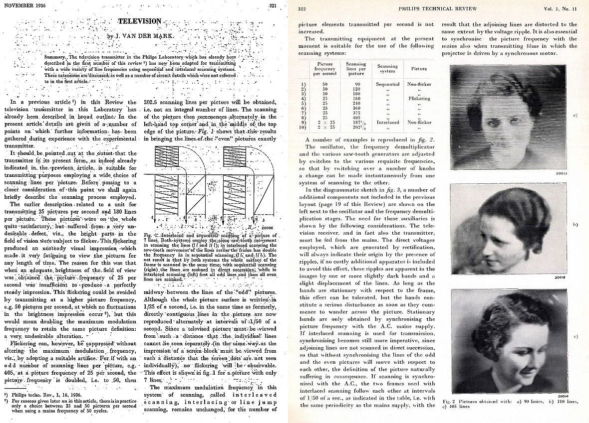
Looking at a photograph of a 240 line Baird image it appears to compare quite favourably with the 405 line EMI images (above) but what you are not seeing in the still photograph is the very noticeable flicker from the Baird 25 Hz frame rate. See how engineers at Philips perceived flicker in November 1936 here. Further information on interlacing and flicker reduction can be found in Paul Marshall's article Interlacing - the hidden story of 1920s video compression technology Unfortunately flicker was not the only defect to affect the Baird transmissions. The image below may be flattering the Baird standard. A. C. Cossor Ltd were particularly concerned with departures from the published waveform and complained of the following: 1. Line sync pulses with exponential falling edges that initially rose to black level followed by another rise and fall resulting in a black strip down the left hand side of the picture. 2. The holes in the scanning discs were not spaced equally resulting in ragged verticals. 3. The ratio of picture to sync pulse should have been 60:40 but in practice ranged from 50:50 to 40:60 resulting in insufficient contrast. 4. The frame pulses lasted for 23 lines instead of the 12 specified and there was no black barrier following the frame pulses. Apart from the above complaints from Cossor Ltd what else caused the Baird system to be dropped? Basically Baird Television Limited (BTL) did not have a viable camera and was left experimenting with three different camera systems that all had serious disadvantages. The Farnsworth camera was probably the system that offered the greatest potential but in 1936 this camera had poor sensitivity and problems with picture geometry. The intermediate film camera was tied to a very cumbersome rapid development and scanning system that had very obvious problems with scanning hole blockage and poor sound due to bubbles in the wet processing and if these problems were not enough it was limited by the 1000ft capacity of the film magazines which meant that the maximum duration of any "live" program was 20 minutes. After that you would need to take time to change the film magazine and fill in with another source of material which in BTL's case could be telecine or the spotlight head and shoulders studio or Farnsworth. Apart from the unattractive environment of complete darkness and staring into a powerful scanning light in the spotlight studio, the development delay of 54 seconds between live action and actual television transmission in the intermediate film system meant that announcements in the spotlight studio had to be timed to end taking account of the delay. Leaving aside the amazing German engineering of the intermediate film system and comparing it to directing a cinema film there is a very significant difference. With cinema filming you can retake the scenes you are not happy with but with "live" television you can't and with intermediate film you can't even view what you are currently televising. All in all a total nightmare for program makers before you even consider the limitation of single fixed position camera operation. A further problem was continuity. The stage make-up for the spotlight studio was totally different to that for the main IF studio. The one advantage that the BTL system had over the EMI system was the lack of the image shading that required tilt and bend adjustments. This was especially true in the case of film transmissions where scene changes could be less predictable than those in the television studio.
You can get an impression of the 240 line / 25 Hz flicker in this simulation: I think it works best if your PC display is set to 50Hz rather than the default 60Hz.
Another try at
an actual 240 line recording.
The video below
is 405 line from the PC graphics card
After the war
and taking account of the
1943 Hankey Report of the Television Committee the BBC in 1946
restarted television broadcasting using the existing pre-war 405 line
standards.
The video below shows part of the
1946 BBC demo film converted to 405 lines in a PC
graphics card and modulator to channel 1 and presented on
a 1937 HMV901 television. It was recorded using an HDV camcorder but
unfortunately despite using a slower shutter speed aliasing bars
periodically run up through the picture. These are not present on the
television screen. The cathode ray tube has no ion trap or aluminising
of the screen hence the slightly brown colouring in the centre of the
picture.
Did the BBC provide the world's first regular high
definition television service ?
That depends on how you
define HD.
|
|
.jpg)
.jpg)
.gif)

.jpg)