Peter's Nostalgia Site
If viewing with a smart
phone or tablet then turn it sideways for a better view.
Text in blue/pink are hyperlinks. Click on these for further information.
|
Peter's Nostalgia Site
Text in blue/pink are hyperlinks. Click on these for further information.
|
|
|
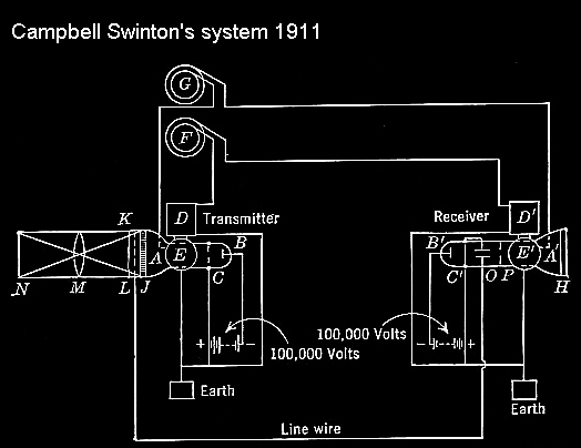
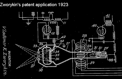
The Emitron Camera Origins Perhaps the earliest relevant description of a CRT based television camera is that of A. A. Campbell Swinton. This was first described in a letter to "Nature, June 1908" and illustrated in his presidential address to the Roentgen Society in 1911 and clearly influenced Vladimir Zworykin's thinking when in 1923 he applied to patent his first embodiment of the iconoscope camera. The significant difference is that by 1923 the triode valve was available to translate Campbell Swinton's scheme into a workable system. A patent is not an idea. A patent needs to be a description of an actual working device so it would not have been possible for Campbell Swinton to obtain a patent in 1911. See also what Wireless World said in December 1935. Campbell Swinton describes the screen J as gas tight and formed of a number of small metallic cubes insulated from each other but presenting a clean metallic surface to the cathode rays on the one side and to a suitable gas or vapour, e.g. sodium vapour on the other. The metallic cubes are made from a metal such as rubidium which is strongly active photoelectrically in readily discharging negative electricity under the influence of light. The receptacle K filled with e.g. sodium vapour, conducts negative electricity more readily under the influence of light than in dark. Parallel to the screen J is a metallic gauze L and the optical image is projected through the gauze onto the screen J through the vapour contained in K. Zworykin's camera also relies on conduction through a vapour between a matrix of globules 36 insulated from each other and a grid 39 that provides the output signal. The globules being scanned by the electron beam. In this case the receptacle 33 is filled with argon vapour.
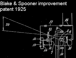
At first sight it might be thought that neither Campbell Swinton's nor Zworykin's embodiments utilised charge storage . In fact the conductivity of the vapour is altered by the presence of light passing through it and Campbell Swinton distinguishes between his embodiment and others using a single photo cell instead of a matrix, pointing out that the single cell needs to respond to the rapid changes of the line scan whereas with the matrix of cells each need only respond to changes at frame rate and that slowness of response (or charge storage) is an advantage. For further information on A. A. Campbell-Swinton see Paul Marshall's article One Hundred Years of All-Electronic Television In 1925 Blake and Spooner patented "Improvements in or relating to Apparatus for Television" (see below) using a single sided camera tube. Whilst they didn't claim charge storage their configuration would appear better suited to provide it. That of Kalman Tihanyi filed in 1929 was double sided and did claim charge storage. See also from 405 Alive. These improvements may have prompted Zworykin to revise his Iconoscope.
By 1930 various techniques had been tried to segment the signal plate into the many "pixels" necessary for a finely detailed image. Some tried evaporation of photo-sensitive material through a fine mesh (as pictured below??) whilst others tried scribing the plate to separate the elements but in 1931 RCA technician Sanford Essig accidentally over baked an evaporated plate. Examination under a microscope showed that the baking had caused the silver layer to divide into a myriad of globules of minute size thus obviating any need for meshes or scribed surfaces and ideal for good resolution.
By 1933 Zworykin had developed his camera to use a single sided photosenitive mosaic and could demonstrate 120 line sequentially scanned television with a frame rate of 24 frames/sec. In July of that year R.C. Ballard of RCA had patented interlaced scanning and by late 1934 Zworykin was demonstrating 343 line interlaced scanning with a 30/60 fps frame rate. The ownership of the RCA, HMV, EMI and Marconi companies was highly interlinked and patent rights were shared. Initially EMI only expressed an interest in television receivers that being the type of volume market they were accustomed to. Whilst not in the company's official remit Tedham and McGee in Isaac Shoenberg's television development team succeeded in building and patenting a very crude front scanned camera similar to Blake and Spooner's in 1932. Perhaps due to the formation of Marconi-EMI and the requirements of the Television Committee to supply a complete television system Shoenberg officially set camera development in motion in mid 1933 and by February 1935 they were able to demonstrate a prototype Emitron camera using 240 line sequential scanning and 25 f.p.s. By October 1935 the Emitron had advanced to the standard that was to be adopted in Britain for decades to come, namely 405 line interlaced with 25/50 f.p.s. Despite the exchange of patents between RCA and Marconi-EMI there does appear to have been a certain secrecy and rivalry that required the British company to devise their own manufacturing methods for the Emitron. The detail of how to manufacture such items as the mosaic was not revealed by patents at the time. Whilst the RCA Iconoscope and Marconi-EMI Emitron have great similarities they were clearly manufactured using different processes. The first Iconoscopes used a side entry in order to mount the mosaic whereas the Emitron used a rear entry and a different system of mounting. Later Iconoscopes used a large diameter cylinder rather than the spherical body. In the journal "Electronics" H.M. Lewis of the Hazeltine Corporation gives his opinion of the current standards used in the US and Britain. "Standards in Television".
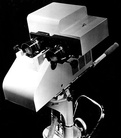
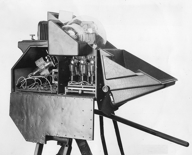
The short neck Emitron Camera...........................................Below is the 1934 RCA camera fitted with a tube as above.
In the basic Emitron a photosenitive mosaic is illuminated by the focussed optical image. The mosaic is typically a thin mica sheet the image surface being covered in minute photosensitive blobs that are electrically insulated from each other and the reverse surface covered in a uniform conducting layer or back plate. The output signal is taken as the voltage difference between the back plate and the final anode of the electron gun used to scan the photosensitive (front) face where a resistor connects the plate to the anode. The elements of the front face emit electrons when exposed to light but they also generate secondary electrons when bombarded by the stream from the electron gun. The number of secondary electrons can be 5 times as many as those received from the stream. The effect of this secondary emission is that an element in the electron beam loses more electrons than it gains from the beam and thus becomes positively charged. If the emitted electrons are captured by the final anode then the element will rise in voltage relative to the anode. When this rise in voltage results in the element nearing or exceeding the anode voltage no further rise will take place and a state of equilibrium will exist where the beam electrons are matched by those returning to the anode. The secondary electrons not reaching the anode fall back onto other parts of the photosensitive surface. Points not under the beam lose charge due to the (negative) electrons falling on them but these also tend to a state of equilibrium because electrons returning to the surface fall only on the more positive parts of the mosaic. In practice the scanning beam raises the voltage of the surface by about +4 volts relative to the anode and points behind the beam progressively lose voltage down to a level of about -1.5 volts relative to the anode. The diagrams below attempt to represent the wave of voltage caused by the beam scanning the mosaic elements.
Where the mosaic surface has been exposed to light its front surface emits electrons some of which will be captured by the anode and so the voltage at that point will be more positive than areas in darkness. The scanning beam drives all parts of the surface to the equilibrium point (+4 volts) and each area of the surface can be considered as a small capacitor relative to the back plate with the current flow to change the charge dependent on the voltage of the surface immediately prior to the beam arrival and thus relative to the light level since last scanned. As illustrated in Television & Short Wave World
As the beam passes along there will be a positive wave of voltage following it and many of the secondary electrons emitted from the photosensitive elements under the beam will be attracted to the immediate area just scanned because it will be slightly more positive than the anode voltage. However, the situation is rather different when you consider the start of each scan line. At these points there will be no closely adjacent area that has just been scanned so rather than the secondary electrons being attracted back to the mosaic surface they will tend to flow to the anode. The output signal from the mosaic backplate is referenced to the anode voltage and so the greater flow of electrons to the anode makes the anode less positive thus drawing the output signal towards black. See waveforms below. This effect can be approximated by adding a combination of a ramp signal (tilt) and a parabolic signal (bend) to a normal video waveform resulting in a line scan that is generally dark on the left and gradually brightened towards the right side of the picture. In practice the Emitron output signal was manually adjusted by adding these shaping signals in opposition to the unwanted shading. It was necessary for an operator to readjust the levels of tilt and bend signals that resulted from changes in picture content. The same effect described above for line scanning was also present over the duration of the frame so a separate pair of tilt and bend controls were also required to remove vertical shading. Below the uncorrected Line (top left) and Frame (top right) signals as they appear from the mosaic signal plate are shown along with the corrected Line (bottom left) and Frame (bottom right) as at the outputs of the A,B and C amplifiers. The screen image below shows the effect of uncorrected tilt and bend although in contrast to the example frame waveform this image shows the more typical darker at the top characteristic. Click on the picture below to see Blumlein & Browne's patent.
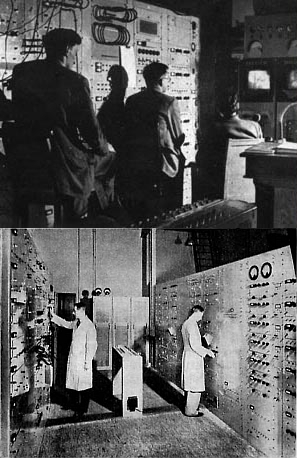
Note that black is at the top in each waveform and that the strong negative going (white) impulses are not sync. pulses but are spurious video signals generated by the mosaic during line and frame flybacks. A suppression mixer in the transmission system applies cancellation pulses in the flyback periods that return/maintain the video signal at black level prior to the addition of the actual line and frame sync. pulses. The photo below shows the Marconi-EMI camera control racks in March 1936.
The March 1936 photo above was probably taken at the Hayes factory. .................Camera cables were massive. The racks were arranged differently when installed at Alexandra Palace. The vision equipment is on the left with all the tilt and bend controls up close to the monitors and the sound equipment on the right. Bottom right is the view from the monitor end taken before the heat extraction hoods were fitted. Click on the photo below for a detailed description of the studios and equipment from the IEE Journal December 1938. Note that this article is historical and also covers the Baird equipment that was discontinued in early 1937.
Short and Long Neck Emitrons The first Emitron tubes had short anode assemblies but electrons hitting the anode walls released secondary electrons that detracted from the focussed beam. Later tubes had an improved arrangement of first and second anodes that reduced the release of secondary electrons but required a longer assembly. Below is a short neck production example (left) and a long neck complete with scan coils.
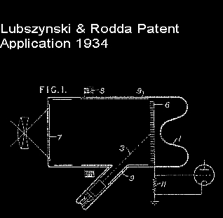
.JPG) .JPG) The first Emitron cameras used a 6.5" lens. This is approximately equivalent in 35 mm camera terms to a focal length of 47 mm. The lens had an f3 full aperture and if focussed 3 feet away would have a rather limited depth of focus of approximately 4". If you stopped the lens down to get 6" the illumination would need to be quadrupled which would generally be unacceptable to the subject. The substantially shorter focal lengths possible with the Super Emitron greatly improved things. A full technical description of the Emitron camera can be found here. The shortcomings of the original Iconoscope/Emitron led the EMI team to devise an improved design with a separation of the functions of photosensitivity and charge storage. LLubszynski and Rodda working in Shoenberg's team applied for a UK patent (442666) in May 1934 titled "Improvements in or Relating to Television" and this was granted in Feb 1936.
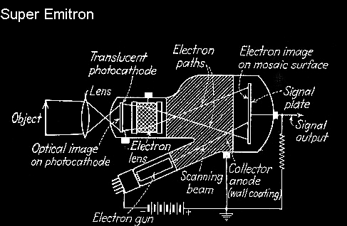
In the Iconoscope and Emitron described above the light sensitive elements are located on the scanned signal plate. In the absence of scanning, electrons are emitted from areas of the scanned plate that are optically illuminated thus building a stored charge representation of the optical image. Secondary electrons emitted from the mosaic during scanning tend to dilute and distort the stored charge image. In the Super Emitron the photosensitive element is separate from the mosaic and the stored charge image is intensified by secondary emission. The optical image is no longer focussed on the mosaic. It is focussed on a translucent photocathode as shown in the diagram below. This photocathode is not segmented but has an homogenous coating on its inner surface. This coating generates an electron image with higher emission in areas of high incident light. An electron lens is mounted between the photocathode and the scanned mosaic. The lens serving to project an enlarged and focussed electron image on the mosaic. The paths of the electrons travelling between the photocathode and the mosaic are not actually the same as beams of light but rather they trace out a spiral path in this case twisting the image approximately 45 degrees clockwise. The electrons are accelerated by a significant potential difference and cause substantial secondary emission on hitting the mosaic thus creating a much greater charge image than is generated in the standard Emitron so the undesirable effects of secondary emission resulting from the electron scanning beam are relatively lessened. A further significant benefit of the Super Emitron is that the optical focus plane can be very much nearer to the lens thus permitting lenses with shorter focal length giving greater depth of field. For further information and photos of Emitron cameras and equipment see the Museum of the Broadcast Television Camera See also the Broadcast Engineering Conservation Group.See
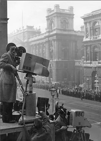
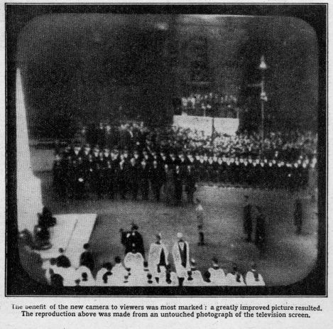
Note the bulge on the side of the camera accommodating the 45 degree electron gun. Whilst the Super Emitron gave advantages in terms of tilt and bend and a significant improvement in sensitivity, in a paper presented to the IEE in late 1938 McGee and Lubszynski described how this type of camera was chiefly used for outdoor transmissions because a distortion of the image tended to be more obvious in studio scenes where straight lines and rectangular objects were more prevalent. The Super Emitron with its side projection was first used by the BBC in November 1937 for televising the armistice ceremony at the Cenotaph in conjunction with a long nose Emitron. The distortion is far from obvious in the screen image.
After the war in 1946 the BBC restarted television broadcasting using the same 405 line standard and this continued until the early 1980s. You can see some of the factors involved in deciding to continue with this standard after the war here. The following film clip was used for trade test transmissions in the hours not covered by normal program transmissions. You can see the EMI control room and control gallery in operation. The video below was filmed from the screen of the 1937 HMV901 featured here. .jpg)
In 1961 after 25 years of the BBC Television Service they published the BBC Engineering Monograph No.39 giving some of the engineering history and current development. Finally a link to an interesting article by Andrew Emmerson on Revisionist History. |
|
.jpg)
.JPG)
.jpg)
.jpg)
.jpg)
.jpg)
.JPG)
.JPG)
.jpg)
.jpg)