
Peter's Nostalgia Site
If viewing with a smart
phone or tablet then turn it sideways for a better view.
Text in blue/pink are hyperlinks. Click on these for further information.
|
Peter's Nostalgia Site
Text in blue/pink are hyperlinks. Click on these for further information.
|
|
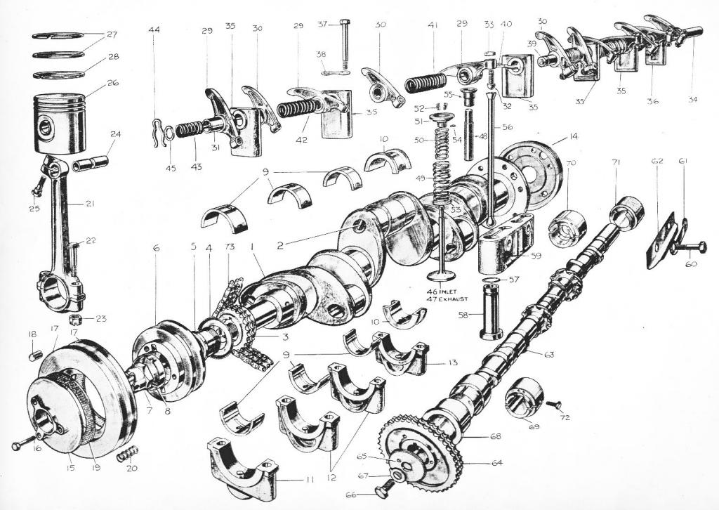
Rebuilding the Engine and Rear Axle of an MG SA Ken Page, the owner of SA 2983, Reg. GRB988 and I recently rebuilt the engine of this car. Our starting point was an engine that had been dismantled many years ago and as you can imagine there was quite a bit of searching around for parts, not the least of which was finding suitable metric fine screws and nuts. Throughout the rebuild we would have had many long delays had it not been for the help of Gary Perry of the SVW Register, for which we are very grateful. Starting with the basics Gary was able to supply a crank already reground and a set of white metalled rods to fit. This late production car was originally fitted with shell bearings but we felt that future maintenance would be simpler with white metal. Gary also supplied us with new old stock (NOS) camshaft bearings. The only bearings that we needed to deal with were the mains and these were remetalled for us by JEL Engineering. NOS pistons also came from Gary.
Engine Services of Rosewell rebored the block, fitted a helicoil for one of the head studs and skimmed the top deck. The original cylinder head had very bad valve seats but we were fortunate to also have a spare head. This had reasonable seats but badly worn guides so it was also sent to Engine Services for new guides and a refacing of the seats and mild skim of the head. The set of rods that we had were not really a set so we balanced them as best we could by grinding material from the lumps on the big end caps. We also got Engine Services to balance the crank and flywheel. Given that straight sixes are balanced by mirroring the imbalance of two back to back three cylinder engines we fitted our heaviest two rods in slots three and four, then next heaviest in two and five and the lightest in one and six. I couldn't see a FRONT marking on the pistons and stupidly fitted them the wrong way around before eventually finding that there was a FRONT mark after all and, needless to say, we had them all the wrong way around. We had, however, fitted the rods the correct way around so it wasn't just a simple case of twisting them to face the other way. We had to take each piston out again and heat it in a bucket of very hot water to get the gudgeon pin out, then swap the piston round and re-install. Those clamp bolts are pain too. We needed to grind a chamfer on our socket spanner to prevent it fouling on the rod as we tightened the bolt. I've done quite a lot of re-builds on SS Jaguar straight sixes and these have seven main bearings so it was a nice change to get the easier access for the ring compressor that comes from the SA only having four mains. After fitting the crank we mounted the front plate and aligned the crank and the camshaft to give us the correct number of chain links between sprocket markings, a task that proved easier than I expected. After making and fitting a new locking tab for the camshaft sprocket we offered up the chain case but were much puzzled by the fact that the spiral groove on the collar that fits over the crank and through the oil seal doesn't wipe on anything! It's not adjacent to the seal and has nothing surrounding it. Ignoring this mystery we then attempted to close up the chain case only to discover that the bolts are only threaded into the rather thin front plate and needless to say, there were several front plate holes with stripped threads. Why these were not threaded into the cylinder block is quite beyond my understanding.
Next we tackled the flywheel end. The flywheel casing was fitted without drama after we managed to source a complete set of bolts. Then we mounted the flywheel and secured it with an original set of bolts. I didn't know what torque to use but given that they were the same diameter as the equivalent flywheel bolts on the SS Jaguar I used the 80 lb-ft figure that I was used to. Unfortunately one of the bolts wasn't game for this torque and severed about half way down with nothing protruding from the crankshaft. Fortunately it wasn't tight in the threads and I managed to poke it around a few turns to get a grip of it. With flywheel fitted using a new set of bolts and the clutch assembled we now turned our attention to the oil pump. On disassembling the pump that came with the engine we found that the gear teeth were rather pitted and there were no Woodruff keys fitted to its drive shaft so we cleaned up a rather nice NOS pump that we had. It was only after securing the outer four bolts that we discovered that the inner four on this pump were about half a bolt diameter further apart!. Very subtle but incompatible with our block so we transferred the innards of the NOS pump into our old body. Our oil strainer was missing its felt seal on the pivot point and needed its strainer gauze replaced but otherwise presented no problems. After making a nice thick sump gasket from Millboard the sump with its surge plates was fitted leaving us just to deal with the oil gauge sender. Our's was seized up and the terminal screw broken off and the float in pieces so we modified the arm on a petrol tank sender and fitted that instead. At this stage we decided to fit the gearbox and mount the assembly in the chassis. Clearly the oil bath clutch housing needs to be fully gasketed and knowing that fitting gearboxes to clutches can be a fit fiddly we thought it wise to offer the two together before attempting it with our carefully crafted paper gasket. After slight initial puzzlement about the clutch operating lever fouling the engine mounting it dawned on us that we could get the release fingers over the bearing if we just rotated the whole bellhousing/gearbox whilst entering it. This achieved, sans gasket and with still having about an inch of gap between bell housing and clutch housing we figured that it might even be possible to slip the large peripheral gasket over the gearbox and bellhousing. Gasket compound was applied to the two mating surfaces and with great care we succeeded in getting the gasket in place without tearing it. Much relief all round! A couple of little doubts and worries then came over us when it was apparent that the gap at the bottom of the bellhousing wasn't quite closed despite tightened bolts. Also, the clutch operating lever appeared to be unmoveable! Horrible thoughts of having to undo everything and remake the gasket were then spinning in our heads but after examining another clutch assembly we decided that we couldn't have fitted it wrong. A half turn of the crankshaft resolved the clutch withdrawal issue and the discovery that the unthreaded part of the lower set screws was too long solved the gap issue. Fitting the engine and gearbox into the chassis frame was reasonably painless after we figured the correct way to attach the gearbox mounting bracket. At this stage cork gaskets were made for the engine side covers and the oil filter bowl and these then fitted. The cylinder head was offered up after fitting the studs. Just placing the head gasket on the top of the studs gives a good indication of any studs that need a little sideways tap to straighten them up. I then applied jointing compound to the lower side of the gasket then sat it on the tops of the studs whilst applying it to the top surface. It was only after lowering it in position that I spotted one little water passage in the gasket that corresponded with a blank area of top deck. Yes, sure enough, at the other end of the gasket there was a blank area covering a water passage on the block! Doh! Fortunately it was easy to lift it off and turn it correct side up. Maybe there was a TOP marking on the gasket but true to my piston observations I never found it. We used Blower's tightening order and 50 lb-ft to secure the head and didn't manage to tear any studs out of the block. Before fitting the oil pump connection we used a pump action oil can to fill the pump and then after fitting the the main oil pipes we filled them through the rocker feed connection. We had already filled the oil filter assembly and the sump with oil. On turning the engine over it was nice and reassuring to see oil emerging from the rocker feed pipe.
With valve clearances set and manifolds and carbs installed we worked out what was the most convenient orientation for the distributor body then wired up the plugs to suit. Having established top dead centre (TDC) we found a sensible position for sparks to occur and then filled the float bowls with petrol. With choke applied our first turn of the starter got us a cough and the second got nice smooth running on all six. Until we get the car out on the road it's a bit early to say but first impressions are that our balancing efforts have worked as the engine feels very nice and smooth with no unwanted noises.
Rebuilding the Rear Axle As received the rear axle leaked oil from both sides of the banjo and was a real growler! At some time in the past someone had clearly attempted to adjust the pinion meshing and when we came to it the pinion was stiff to turn and felt lumpy as you rotated the input shaft. We needed to remove the diff. unit to replace the banjo gasket anyway so a proper examination of the internals commenced. We thought that resetting the tooth meshing of the crown wheel and pinion might sort things but after various attempts to achieve correct meshing we concluded that the bearings needed to be replaced. Our first thoughts were that the lumpy roughness must be due to the rear pinion bearing but after separating the diff. assembly from the pinion casing it was clear that the pinion bearing was smooth and free from play after relieving it from its excessively tightened penetration. The real problem was the ball bearings holding the crown wheel assembly. It is a little strange that ball bearings were used in this application as there are significant end trusts. Taper roller bearings would seem more appropriate.
Anyway, we fitted new ball races and it was then possible to achieve something like a correct tooth meshing pattern. This had been impossible with the old bearings as I suspect the adjustment range was not able to cope with the excessive side play. With the new bearings the rebuilt assembly is no longer stiff and lumpy and we now have a nice quiet running axle. See also: Rear Axle Overhaul |
.jpg)
.jpg)
.jpg)