I have owned my 2½
litre SS Jaguar saloon since 1993 and covered more than 20,000
miles in her, but from the outset I've been haunted by a
letter
written by Ed Nantes, well known Australian SS expert, to the previous
owner relating his thoughts on the frailty of duralumin con rods.
Throughout my ownership the spectre of a crankcase with a nasty chunk
missing has caused me almost always to limit my revs to less than 3500
rpm and to always change down rather than let the engine labour.
I am now very happy to report that all that is behind me. Last year I
had a very fortuitous conversation at Beaulieu Autojumble with fellow
SS Register member, Tom Chalmers, who was able to help me in my quest
for steel rods. Unfortunately circumstances and my amateurish methods
of engine rebuilding resulted in a few problems. In this article I
hope to explain why it took me three complete strip downs and
reassemblies, the first two resulting in unsatisfactory road tests, to
achieve my goal.
Tom happened to have an engine with steel rods that he had purchased
many years ago, but never used. Although I only needed the rods Tom
very generously parted with the whole engine for only slightly more
than a fair price for the rods alone. There were a few parts missing
from the engine but it generally looked to be in good condition and
after inspecting a big end and a main bearing I decided that it might
be worth installing it, as is, in my car. A timing case, front plate
and flywheel were kindly donated by register member Ken Page and the
early style water manifold by Tom.
My first drive in the car with this engine was a bit of a mixed
experience. The new engine had much higher vibration levels than my
old one and the oil pressure was disappointing after 20 miles at 70
m.p.h. along the Edinburgh city bypass. Perhaps I should have looked
at more than just two of the bearings.
I drained the sump prior to removal but was dismayed to see water
pouring out ahead of the oil. With the sump off, sure enough, I could
see beads of water on the skirts of pistons 3 and 4.
Next I tried to
remove the cylinder head. This required ridiculously large torques to
undo the head nuts and once they were off the head still refused to
move even with the whole weight of the front of the car hanging on it.
Eventually it did give way after a succession of upward hammer blows
to the square boiler plugs protruding from its sides. The studs had
rusted themselves into the head. Subsequent inspection of the head
revealed nothing untoward but on lifting the gasket off the block the
full horror became apparent.
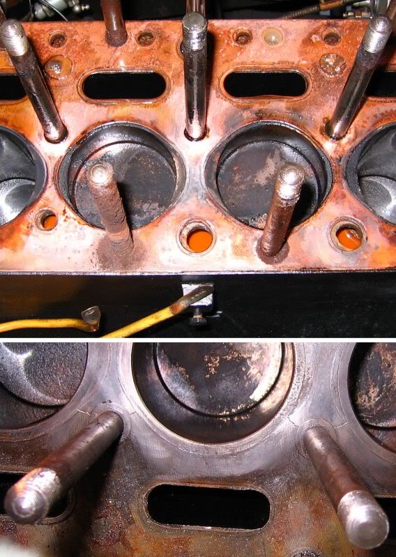
The dreaded corrosion made head removal almost impossible. Liners and stud inserts had weakened the block, hence the cracks
that eventually let water into the oil.
At some time in the distant past this engine had been fitted with
liners and it had also had threaded inserts fitted for the studs.
These two procedures had weakened the top deck of the block which had
fractured in four places between stud inserts and liners.
There was also pitting corrosion on the tops of the liners so at this
point I decided to abandon this block and rebuild my old engine using
the crank and rods from the new one.
The transfer of the crank to my old block was not without problems. My
old block had used a flanged rear main bearing and replacements for
these are not easy to find so after consulting Ed, I decided to
install the later, separate thrust washers and bearings. However,
there was no mechanism to retain the separate washers in my crankcase
so, with Ed’s advice, this was achieved by drilling and using roll
pins.
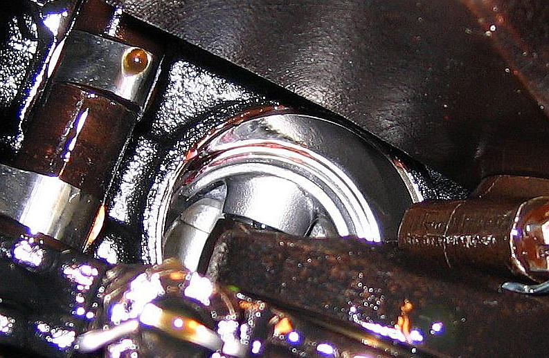
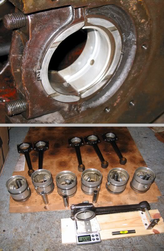
Pinned to the wall, ensuring the thrust washers stayed in place. It
seems to have worked. Con-rod and piston health farm. Home made but effective device for
weighing big and small ends.
After removing all the bearing caps it became apparent that there was
fatigue failure in some of the main shells but on measuring the crank
it appeared not to have significant wear.
I then re-built my old block using my original pistons but with the
crank and rods from the new engine and a completely new set of main
and big end shells. I also used the cylinder head from the new engine
after grinding in its valves, as previously my engine had been using a
post-war cylinder head.
The vibration issue worried me but I didn’t think it could be due to
the crank or the rods. The rods were a proper numbered set and it
seemed likely that these rods and crank were the ones that had been
originally fitted at the factory. The flywheel that I had used when I
first installed the new engine had suffered some corrosion which I
thought could have unbalanced it so for the second re-build I used the
flywheel from my old engine.
I had a very nice complete gasket set with a new unmolested Corrujoint
head gasket so this was duly fitted although I could see that there
were some apertures that didn’t quite line up with block.
Unfortunately, it was only whilst having a lunch break that it dawned
on me that I had fitted it upside down. The Corrujoint gasket actually
looks to be the wrong way up when it is fitted correctly. Needless to
say muggins had torqued it down before the penny dropped so off came
the head again and I was forced to discard my nice gasket and replace
it with another since they are not reusable.
On first start-up there were no problems and with some trepidation I
depressed the clutch mindful of my new thrust washer retention
techniques. Another 20 mile trip along the bypass showed that I still
had a vibration problem despite using nothing new other than the crank
and rods from the engine I had acquired.
At this point I decided that I couldn’t live with the vibrations so
once again I removed the engine.
The cranks of our engines have four balance weights which I would have
expected to be of similar masses but on calculating the masses using
the eureka principle of water displacement it appeared that they were
very dissimilar. As I understand it, our engines can be considered as
two three-cylinder engines where the out of balance forces cancel by
virtue of the mirror symmetry. I just couldn’t see how my shaft could
be given that symmetry without very drastic alteration.
Fortunately, at this point, yet another SS register member, Alan
Logan, came to my rescue with the offer of a nice symmetrical Mark V
crankshaft. The Mark V crank has a slightly longer nose than those
fitted to the earlier cars so some cosmetic surgery was needed in
addition to a re-grind.
For the third engine re-build I decided to get the crank, flywheel and
clutch cover dynamically balanced and I also bought a 1kg digital
scale with 0.1gm resolution to enable me to balance the rods and
pistons.
Ideally the rods should be matched both in terms of rotating mass and
reciprocating mass so I made a little jig to weigh big ends and small
ends separately whilst the rod is maintained horizontal on knife
edges. The big ends have a nice chunk of metal on the bearing cap that
can be ground to achieve rotating balance but the reciprocating masses
are slightly more difficult. To minimise the material loss I first
selected combinations of rods and pistons that got me near to balance
and then to improve on this you can grind material from the inside of the gudgeon pin
hole.
After re-build number 3, test driving my now balanced engine did give
me some joy. It was much smoother than it had ever been when taken
above 3000 r.p.m. but there was still some vibration around 1600 r.p.m.
I had replaced the gearbox mounting when I initially swapped engines
and I wondered if perhaps the chassis and gearbox bolt heads were
touching each other. They weren’t but I did realise at this stage that
the new mounting had rubber with much less compliance than the old
one. Swapping back to the old mounting put a smile on my face but
there was still a small vibration when revving the engine in neutral,
just at 1600 r.p.m.
The strange thing was, that whilst vibration was apparent in the cabin, I
couldn’t detect it simply by holding my hand on the engine. I then attached a
microphone to my laptop and with the aid of a very nice spectrum
analyser freebee I established that the peak
at 1600 did not change frequency when engine revs were changed.
Clearly what I had was a resonance. I still haven’t pinned
down the cause of the
resonance but in normal driving the resonance is not apparent, only
when free revving in neutral can I detect it, so I will just live with
this for the time being.
Since writing the above
I have made a little progress on the vibration issue.
I decided to investigate the mounting of the clutch and flywheel just
in case the dynamic balancing had perhaps been carried out imperfectly
and I had assembled them in a different angular position relative to
the crankshaft. To this end I removed the gearbox with a view to
running the engine with clutch and flywheel assembled in the
alternative positions and comparing vibration levels. The rear of the
engine was mounted on a pile of bricks with the gearbox rubber mount
on the top of the pile. In the end I didn't swap the position of the
flywheel although I did try both orientations of the clutch cover. My
reason for not pursuing this further was because I just couldn't
detect the vibration at all.
I then reassembled the car and purchased a small electronic
accelerometer and wired it up for connection to my laptop (for use
with the spectrum analysis program). However, by the time I had
assembled the accelerometer I had clocked up a further 1000 miles in
the car and the vibration has now become barely detectable even at its
favourite 1600 rpm speed so the accelerometer has been shunted into a
drawer and my inclination to remove the gearbox again has waned.

.jpg)