In "The Automobile
Engineer" October 1937 the article entitled "The S.S. 2½-Litre
'Jaguar'" states that the S.S. company pioneered the use of the SU
automatic auxiliary starting carburetter. We may at times wish that we
could disable this little device, and some have fitted switches for
this purpose, but there is little doubt that starting the S.S. in 1937
was a rather simpler procedure than that described for starting the 6
cylinder Bentley of ten years previous. Take look at
the Bentley handbook from 1927.
For my own car I tend to favour keeping the starting carb as lean as
possible. If I have used the car the day before then she would normally
start first go but if several days have elapsed then she normally did't fire until the third
jab at the starter button. This has been true over 25 years of ownership on two
traditionally constructed batteries but recently I needed a replacement but the
company I had used was no longer manufacturing "old" batteries. I now have a new
one that looks the same with filler caps and lead inter-cell connecting links
but turns the engine over more vigorously and the engine now starts on first
push of the button. I don't like adding switches to an
original layout but the panel lamp switch on the pre-war cars operates
independently of the lighting switch so I've arranged for it to supply
both panel lamps and starting carb. Once the thermal switch kicks out
then clearly the panel lamp switch just performs its normal function.
Before anyone points it out, I know that in the video I've got the
wrong cylinder head (from a Mark IV) for my SS and the wrong water
manifold but this has now been rectified. The SS manifold is longer
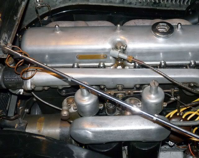
and has the thermal switch on the under side near the front.
The starting carburetter is a separate unit which draws its fuel from
the float chamber of the rear main carburetter. It is activated by the
thermal switch mounted in a slot on the water manifold. This is under
the front end (as in the engine photo above) in earlier cars and on
the side between the two main carburetters in later models.
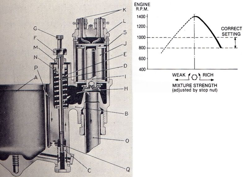
When the device is operated, air is drawn from the atmosphere through
the air intake P and into a chamber at Q and is mixed with fuel
passing through the jet C. The mixture then passes upwards past the
shank of the needle, through a passage, and so past the aperture
provided between the valve H and its seating. From here it passes
directly to the main induction manifold within the cylinder head.
When the solenoid J is energised the iron core I is raised carrying
with it the ball-jointed disc valve against the load of the conical
spring thereby opening the aperture between valve H and its seating.
Any leakage between this valve and its seating would allow the device
to operate when not required and affect the idling setting of the main
carburetters. If the solenoid is energised while the engine is idling
the valve will not normally lift owing to the high manifold
depression; the act of opening the throttle will reduce manifold
depression and allow the device to operate.
The fuel level in the starting carburetter is controlled by the rear
main carburetter float chamber A. It can be seen from the illustration
that this results in a reservoir of fuel remaining in the well of the
starting carburetter. When starting from cold this fuel is drawn into
the induction manifold to provide the necessary rich mixture.
When the valve H has lifted, the needle disc chamber is in direct
communication with the inlet manifold and the depression, dependent on
throttle opening, varies the position of the needle D by exerting a
downward force upon the suction disc N and needle assembly.
Thus:
(a) At idling the relatively high depression will draw the needle into
the jet until
the needle
head G abuts against the adjustable stop F.
(b) At larger throttle openings a reduced depression is communicated
to the
needle disc chamber and the
spring will tend to overcome the downward movement
of the needle thus increasing
mixture strength.
Tuning of the starting carburetter is confined to adjustment of the
stop nut F which limits the downward movement of the needle and is
carried out with the engine running at normal temperature and with the
main carburetters already correctly tuned.
Proceed as follows:
1. Because the engine has reached normal running temperature the
thermostat
will not be energising the solenoid so you
will need to short the thermostat
connection with a separate wire to the
thermostat mounting screws or some other
convenient ground connection.
2. Open the throttle momentarily to allow the valve H to lift.
3. Adjust the stop nut F with reference to the graph as follows:
(a) Turn nut F clockwise (to weaken) until the
engine begins to run erratically.
(b) Then anti-clockwise (to enrich) through the
phase where the engine
speed has
risen markedly to the point where over richness results in
the
engine speed dropping to between 800 and 1,000 rpm with the
exhaust
gases noticeably black in colour.